The Spridget Motor
skip the reading and go right for the pictures
So after the original motor was too far gone, I decided to build up a Spridget motor and gearbox for the car. Why ? well because its a new motor and I can put it into the car without drilling a single hole into my Singer frame, nothing gets cut, nothing gets drilled, its a true drop-in and bolt-in motor/gearbox. After modifications to the motor of course 🙂
First I started out looking for a motor, the local wrecking yard had a 1098cc and a 1275cc motor and I went for the 1098cc not knowing any better. I should have gone for the 1275 as it has many more parts available, for example you can buy a brand new crank for the 1275 but not for the 1098, but of course I don’t expect to break anything like that and pistons/valves/bearings are easily obtained, again I hope never to break those. I spent a hundred bucks on the motor that was sitting in the mud but complete and did a full rebuild on it. I mean full, did not bother with many details like measuring, just went straight out and got new pistons, valves and like that. Ended up with the crank 0.10 over and .20 over pistons as the block already had 10over pistons. I then purchased a new gearbox from a guy on the web and I was ready.
I got some drawings from the U.K. on how to do this and started guessing.
In the following pics, you can see some of the parts I had to make, at this point nothing is finished and nothing is painted, still in the “test fitting” stage. But good progress is being made. I am happy with the change of motor from a original Singer Le Mans motor to this Spridget motor, parts will be available and it will be reliable to use on a nearly daily basis such as to work and back. The gearbox will also make it easier to drive since it will have synchro’s. I even have the option of going to a 5-speed gearbox if I want for better freeway drive-ability. I know many purists will frown upon me and I have even been told I will not experience the pre-war joy of driving but many of the purists don’t live in S. Calif. with its “Get out of the way, if you are only going to drive 75MPH on the freeway” lifestyle and where I live, there is only 1 road in and out of town and its the freeway for 40 miles before I can get off the freeway onto small roads, so new reliable motor it is. The motor is about the same weight and size so its a good fit and will not burden the front suspension.
|
Click on picture to get a larger picture.
|
|
| Here is page 1 of the instructions on how to do this, its not for the faint of heart as it initially appears to not be well documented. Note: clicking on this gets you the full size copy, its not a small file, neither are the rest of the instructions sheets. unless you are really interested you might want to skip clicking on the instructions and scroll down to my pictures | 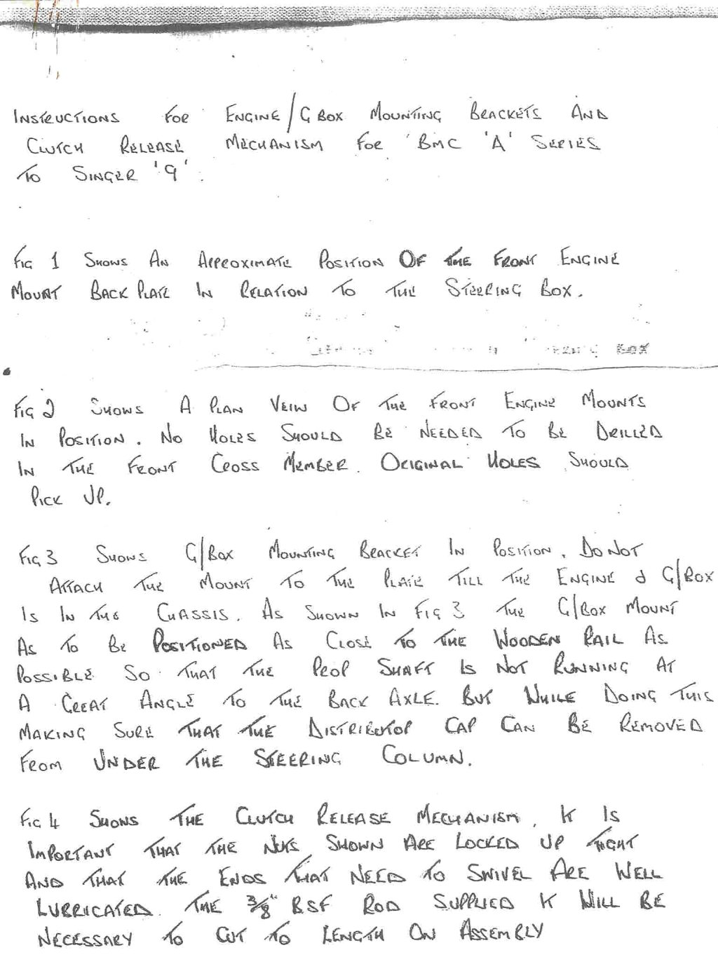 |
| This one confused the daylights out of me, it just made no sense to me (it does now as you will see if you keep reading) What it is, is the front view of the motor and how it all fits with the steering gear on the left side. This is what I could NOT achieve until I found out I had to cut the Sprite/Midget mounting plate. | 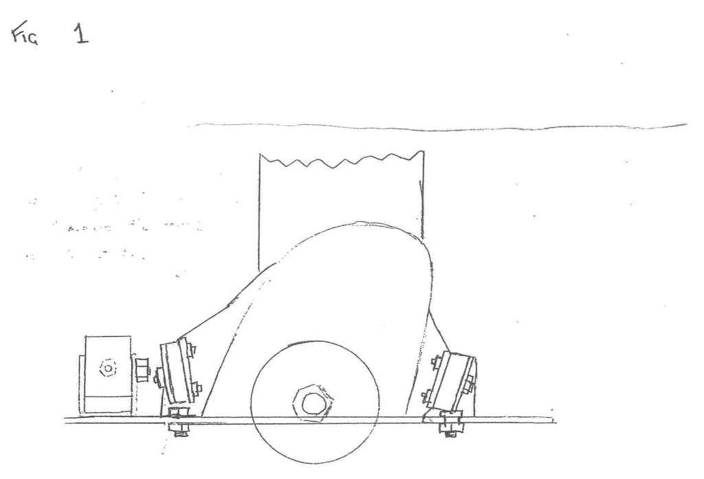 |
| The top view of the front motor mounts | 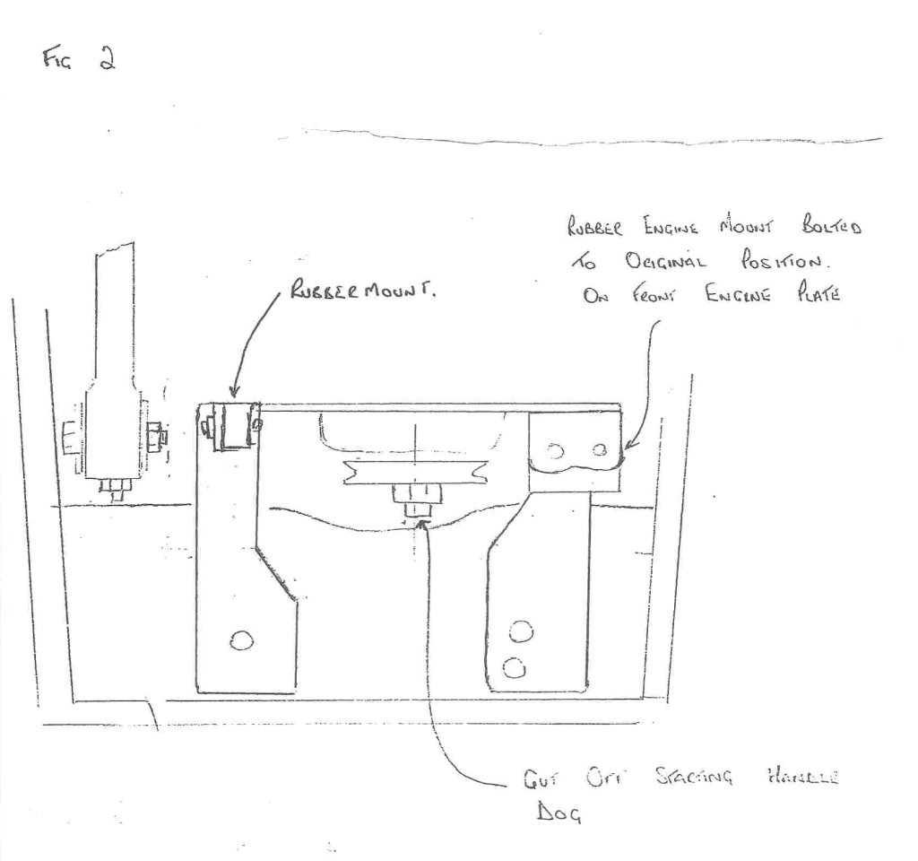 |
| Rear Motor mount with parking brake detail |  |
| A picture that shows the Clutch mechanism and how to make/adjust it. All of a sudden this task of swapping motor was a little daunting. | 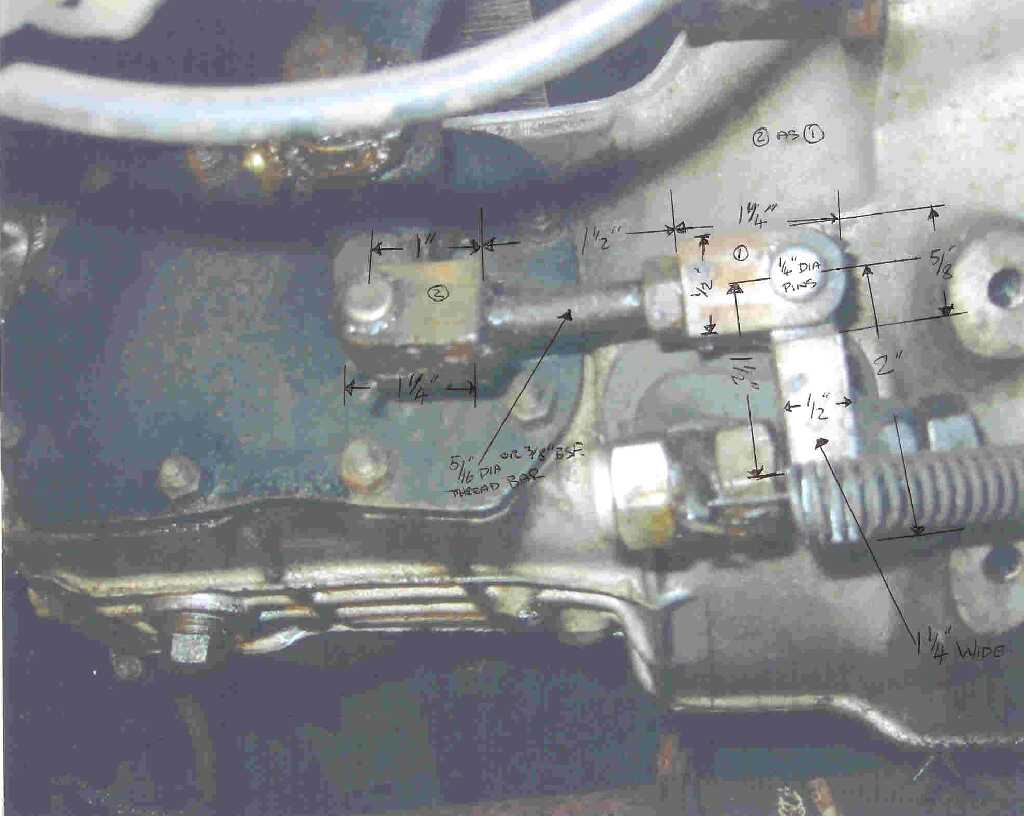 |
| Yup, more work than I thought of when I started, I have no idea why I did not think of the complexities of the clutch lever/mechanism when I thought of swapping, but oh well, too far along now. | 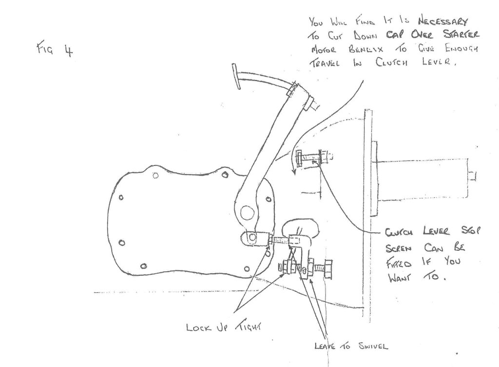 |
| A motor mount, ok this part looks easy but as I worked on this, I really wonder why the cutout, it does not seem needed and leaves more steel in place for strength…see later in discussion on what I did and how. | 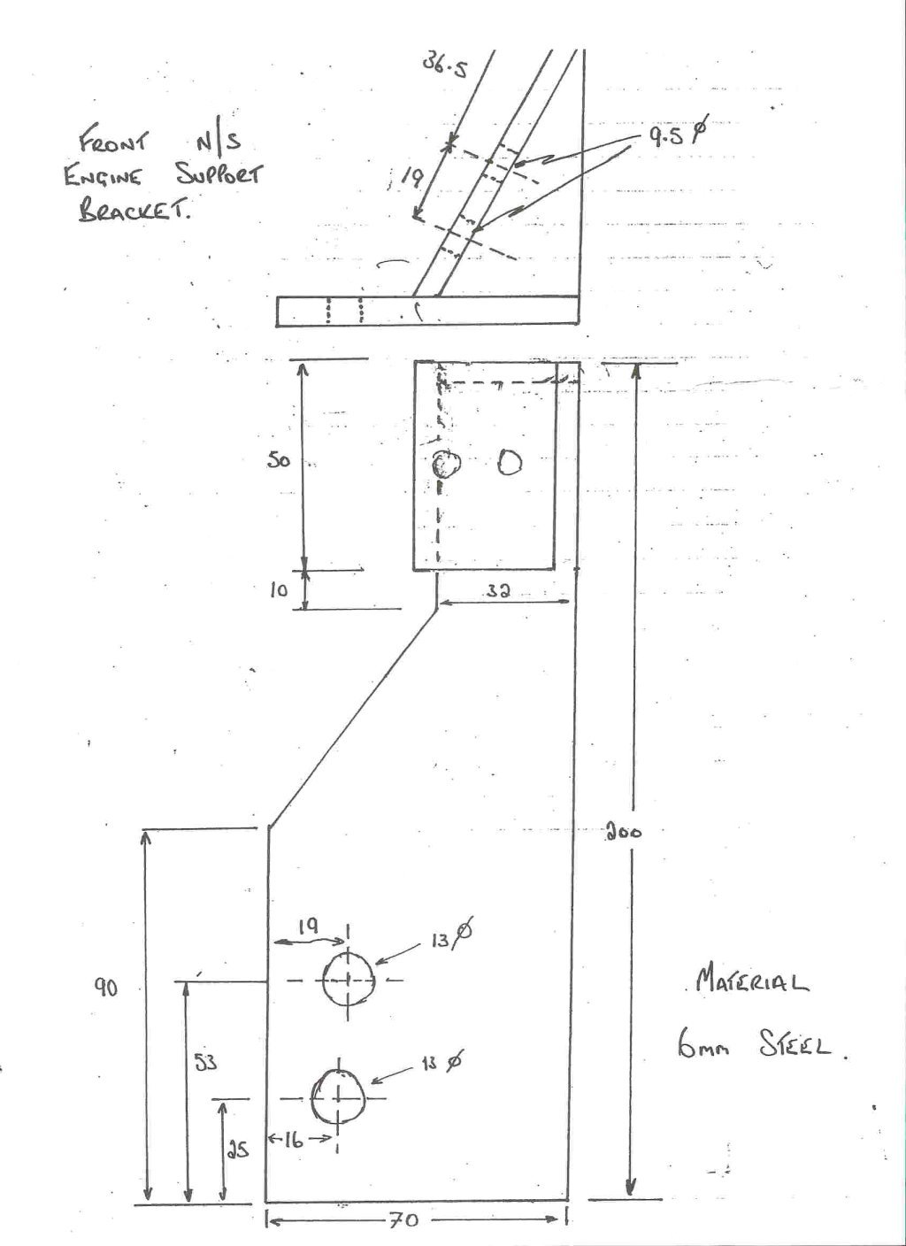 |
| The Rear Motor mount, no questions here…all welded up and ready to go. | 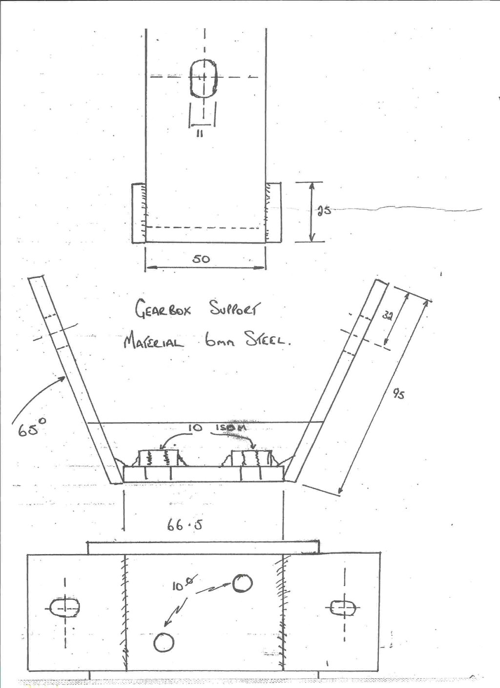 |
| The other side of the front motor mounts, again that taper/cutout makes no sense to me, it weakens the motor mount tremendously and I minimized it to the max. | 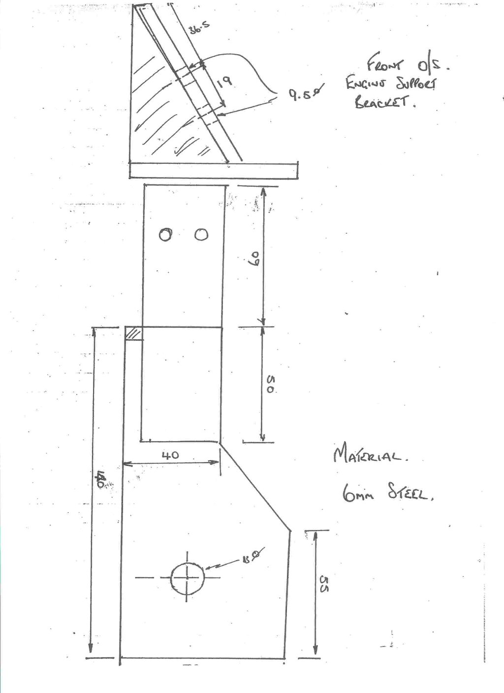 |
| The transmission side plate details, its a cast Alu part on the original gearbox but that won’t be strong enough for the clutch pedal, etc. so its made out of nice strong steel. I was tempted to weld up the parts onto the original Alu part since I could have TIGged it but lets follow the instruction the first time around at least. | 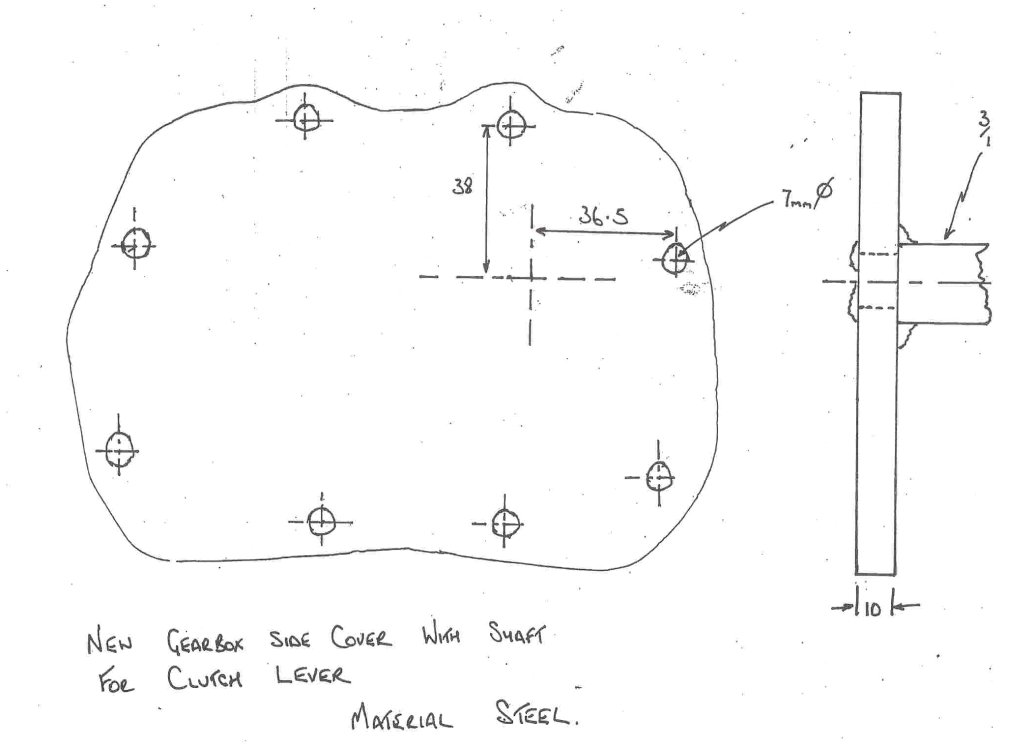 |
| The Carburator linkage, looks interesting. | 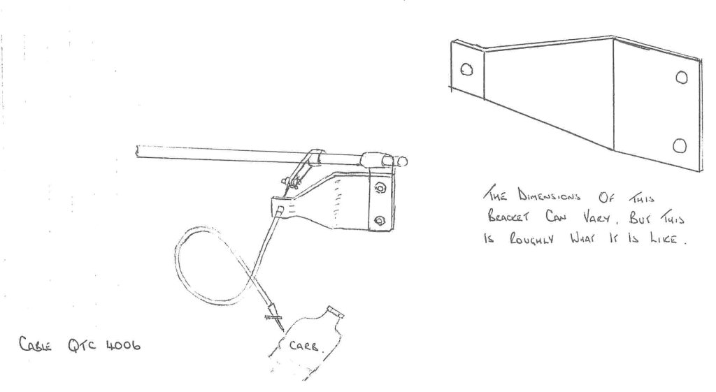 |
| The new motor back from the machine shop and assembled (I lost the pics of the assembly 🙁 ) At this point it is fully rebuilt, new bearings, new valves, new lifters, new pistons, new oil pump, new water pump, new timing chains, sprockets, etc. basically new everything to the of $2,300 for parts alone. | 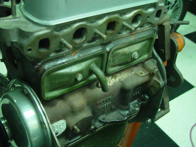 |
| Here it is going into the frame for the first of many times, yes it still needs to be painted, I did not paint it during the rebuild because I still have not decided on the color of the motor. At this point its just going into the frame for some rough fitting of the motor mounts and to make me feel good about some progress. | 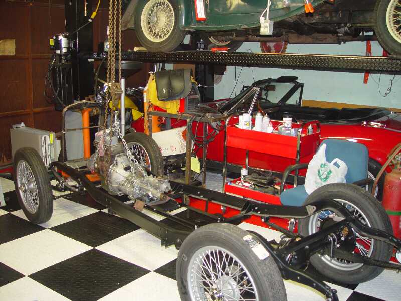 |
| Another view of the motor going into the frame. | 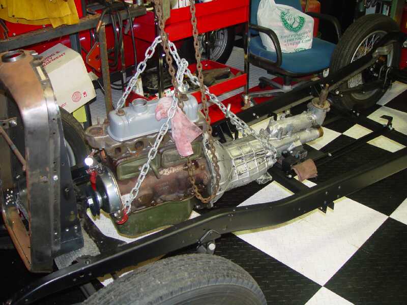 |
| Ok, now we have some issues. The motor is VERY crooked in the frame and I can’t get it to center, something else is wrong and I can’t get it right. I figured I had to cut something and I was right, I have to cut the Spridget from motor plate which is the motor mount and re-weld it. You can click on the picture to see text, I have not cut it yet. | 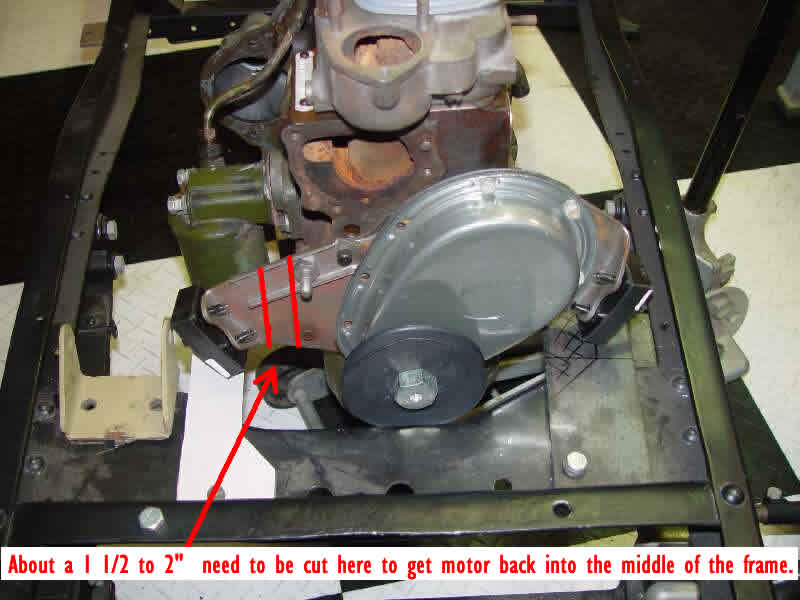 |
| Outside grabbing some S. Calif. sunshine, that is the 4AD on the car trailer under the plastic cover, the 4AD had to make some room in the garage and lived outside for a while. | 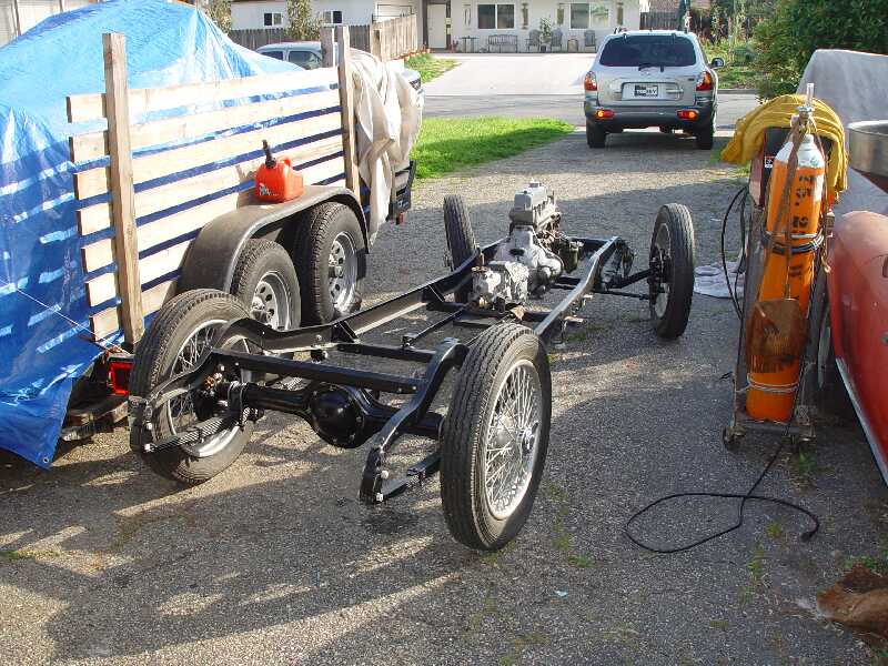 |
| Here you can see the motor mounts are finished up and tacked together, they just need final placing and final welding. You can see the “hash” marks which is where the instructions tell you to cut the 1/4″ plate but I will leave that until later as I want it as thick as possible and it sure looks like the instructions go way too thin to me. | 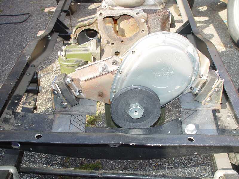 |
| Bad picture of the rear motor mount, too much of that S. Calif. sunshine but you get the idea, its all ready to be powder coated. | 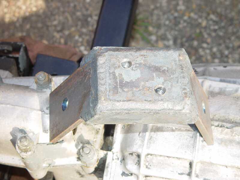 |
| Better picture of the rear motor mount. | 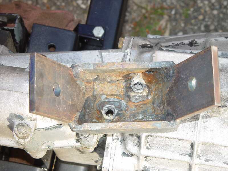 |
![]()